


Phone:
+86-138-0577-0261


Views: 0 Author: Site Editor Publish Time: 2026-09-12 Origin: Site


Sealing flange geometry dictates hermetic seal integrity in modified atmosphere packaging and liquid-tight containers. When a flange deviates even microscopically from a perfectly flat plane, you get micro-leaks. These leaks destroy barrier properties, leading to premature food spoilage and costly retailer rejections. Measuring flexible, thermoformed substrates presents a tough engineering challenge. If you apply physical pressure during inspection, you distort the material. This mechanical distortion hides the exact surface flaws operators need to catch. We must move past subjective visual inspections. You need quantifiable, repeatable measurement methodologies. By comparing contact and non-contact systems, packaging lines can lock down quality control in high-volume production.
A successful heat seal requires three variables to remain perfectly consistent: temperature, dwell time, and pressure. The lidding film must make continuous, uniform contact with the tray flange across the entire perimeter. When the flange is not flat, the sealing anvil cannot apply uniform pressure. High spots receive excessive compression. This thins the sealant layer and causes burn-through. Low spots receive insufficient pressure, creating cold spots where the polymer chains fail to entangle. These undulations create microscopic channels. Even a gap of a few microns allows gas exchange or liquid seepage. To achieve a perfect seal, operators must verify the following physical requirements:
Different packaging applications possess unique failure thresholds for flange deviation. A supermarket fresh tray relies on modified atmosphere packaging (MAP) to extend the shelf life of raw meat and fresh produce. This format requires absolute gas barrier integrity. If the flange warps, oxygen enters the package. You will see rapid oxidation, color degradation, and bacterial growth. Conversely, a food delivery tray demands robust, leak-proof liquid containment. Hot liquids and sauces will quickly exploit any channel leak caused by a wavy flange. This results in spills during transit and severe customer dissatisfaction. Both formats fail catastrophically if the sealing surface lacks dimensional stability.
Flange distortion rarely stems from a single variable. Thermoforming involves heating a polymer sheet to its forming temperature, stretching it over a mold, and cooling it rapidly. Uneven cooling across the mold surface is a primary culprit for warpage. If one side of the tool runs hotter than the other, the polymer shrinks at different rates. Material memory also plays a significant role. Polymers naturally want to return to their original flat sheet state. Residual stress locked inside the PET plastic tray during the stretching phase can release after the part ejects from the mold. This causes the flange to curl or bow. Furthermore, improper trimming operations, such as dull punch tools or misaligned match-metal dies, induce mechanical stress that physically bends the flange out of tolerance.
| Thermoforming Variable | Physical Effect on Flange | Severity of Warpage |
|---|---|---|
| Uneven Mold Cooling | Differential shrinkage causing global bowing across the tray length. | High |
| Excessive Material Memory | Corners curling upward as the polymer attempts to revert to a flat sheet. | Medium to High |
| Dull Trimming Tools | Localized mechanical stress causing ripples or burrs along the cut edge. | Medium |
| Improper Stacking | Compression distortion while parts are still warm from the mold. | Low to Medium |
In Geometric Dimensioning and Tolerancing (GD&T), flatness is a form control that dictates how much a surface can deviate from a perfectly flat plane. It is defined by two parallel planes. The entire flange surface must lie entirely within the space between these two planes. Establishing baseline tolerances for a plastic tray depends heavily on the elasticity of the lidding film and the thickness of the sealant layer. A thick, highly compressible sealant layer might tolerate a flatness deviation of 0.010 inches. However, a thin, rigid film might require the flange to remain flat within 0.003 inches to guarantee a hermetic seal. You must define these tolerances before setting up any measurement equipment.
A widespread misconception on the shop floor is equating material thickness with surface flatness. Measuring flange thickness simply determines the distance between the top and bottom surfaces of the material. A flange can possess perfectly uniform thickness around its entire perimeter but still warp dramatically like a potato chip. Flatness evaluates the topography of the top sealing surface relative to itself. It ignores the bottom surface entirely. Relying solely on thickness measurements provides a false sense of security regarding seal integrity. You can have a perfectly thick flange that still fails every leak test because it waves up and down.
Despite the critical difference between thickness and flatness, thickness checks still serve a practical purpose on the production floor. Operators can use a calibrated micrometer to check the thickness in multiple places against published material tolerances. If the flange thickness varies wildly—for instance, measuring 0.015 inches on one corner and 0.008 inches on another—the part is fundamentally defective. This rapid preliminary step allows quality control personnel to immediately "flunk" a severely malformed flange. You save time by discarding obvious rejects before investing effort in complex, time-consuming flatness measurements.
The most significant technical challenge in measuring thermoformed parts lies in establishing a reliable datum plane. Flexible, non-rigid 3D objects do not sit perfectly flat on a granite surface plate. Gravity alone can cause a thin-gauge container to sag or twist. To measure true flatness, you must establish a reference plane that mimics how the part will be supported during the actual heat-sealing process. This requires custom fixturing that supports the underside of the flange without forcing the top surface into an artificial plane. If your datum plane is wrong, your flatness data is useless.
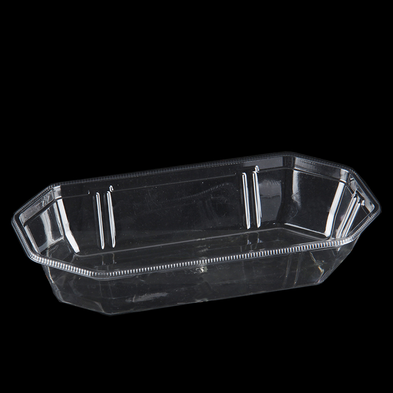
Historically, quality labs relied on surface plates and height gauges to map flange variations. An operator places the container on a certified grade-A granite surface plate. They then sweep a dial indicator or a digital height gauge across the top surface of the flange. The indicator records the high and low points, generating a total indicator reading (TIR). The critical GD&T requirement for this method is that the reference feature must be held perfectly parallel to the measurement axis. If the container rocks or shifts even slightly during the sweep, the resulting data is entirely invalid.
Another manual approach involves placing an inverted flange onto a certified flat reference surface. The inspector places the tray upside down so the sealing surface rests directly against the granite or machined steel plate. The inspector then attempts to slide precision feeler gauges of varying thicknesses into any visible gaps between the flange and the plate. While this method is inexpensive and requires minimal training, it is highly subjective. The operator's tactile feel dictates the measurement. This makes it difficult to achieve repeatable results across different shifts or different personnel.
The primary failure point of all contact measurement methods is mechanical deformation. Thin-gauge polymer packaging is inherently flexible. The physical pressure exerted by the spring-loaded tip of a dial indicator is often enough to compress or bend the flange downward during the measurement sweep. Similarly, forcing a steel feeler gauge under an inverted flange can lift the lightweight container off the reference plate. Both scenarios yield false-positive flatness readings. The measurement tool physically forces the warped part into a flatter state. This hides the actual surface deviations that will ultimately cause seal failures on the packaging line.
Here is exactly how contact methods fail on the shop floor:
To eliminate the deformation risks associated with contact tools, the packaging industry has widely adopted non-contact laser displacement sensors. 2D laser profilers project a precise laser line across the flange perimeter. A camera inside the sensor head captures the reflection, using triangulation to calculate the exact distance to the surface. These systems achieve ultra-precise resolutions, often measuring deviations down to 0.0001 inches. Because the laser never physically touches the part, the flexible substrate remains entirely undisturbed in its natural state. This provides a perfectly accurate topographical map of the sealing surface.
For comprehensive surface analysis, 3D scanning and structured light systems offer unparalleled data density. Instead of measuring a single line, structured light scanners project a series of fringe patterns across the entire container. High-resolution cameras capture how these patterns deform over the three-dimensional geometry. The system acquires millions of distinct data points in seconds, generating a highly detailed point cloud. Advanced metrology software then analyzes this point cloud to identify both global warpage (the overall bow of the tray) and local flatness deviations (small ripples or divots in specific corners).
Investing in non-contact resolution translates directly to measurable operational improvements. High-fidelity topographical data drastically reduces false-reject rates by clearly distinguishing between acceptable natural material variation and critical seal-compromising defects. Non-contact systems enable significantly faster inspection times, reducing quality control bottlenecks. Furthermore, providing maintenance teams with exact, quantifiable data regarding flange topography builds higher confidence in seal tooling alignment. When you know exactly how the flange is behaving, you can optimize the heat-sealing anvil to match.
| Measurement System | Deformation Risk | Data Density | Best Application |
|---|---|---|---|
| Dial Indicators | High | Low (Single Point) | Rigid, thick-walled containers only. |
| Feeler Gauges | High | Low (Edge Only) | Rough preliminary checks. |
| 2D Laser Profilers | Zero | Medium (Line Scan) | High-speed inline perimeter checks. |
| 3D Structured Light | Zero | High (Millions of Points) | Complex offline GD&T analysis and tooling setup. |
Selecting the right measurement system requires balancing inspection cycle times against absolute accuracy. Offline Coordinate Measuring Machine (CMM) inspections equipped with optical heads offer the highest possible accuracy. However, CMM routines are relatively slow, often taking several minutes per part. This delay slows down production feedback loops. Conversely, inline high-speed laser profiling can scan parts in fractions of a second as they move down the conveyor. While slightly less accurate than a lab-grade CMM, inline systems provide immediate, actionable data to prevent the manufacture of thousands of defective parts.
Scaling metrology infrastructure depends on the specific demands of the production environment. Transitioning from batch testing for statistical process control (SPC) to 100% inline automated inspection requires significant planning. High-speed thermoforming lines produce hundreds of parts per minute. Scanning every single part generates massive volumes of digital data. Facilities must assess their network architecture, data storage capabilities, and edge computing power to handle this influx. SPC remains the most cost-effective approach for standard packaging, while 100% inline inspection is generally reserved for high-value or critical-barrier applications.
Modern digital measurement systems integrate seamlessly with facility-wide Quality Management Systems (QMS). Instead of relying on handwritten logs or isolated spreadsheets, optical scanners automatically push measurement data to centralized databases. This integration provides immutable audit trails that link specific flatness measurements to individual production batches, machine settings, and raw material lots. Maintaining this level of digital traceability is essential for complying with stringent food safety standards, such as SQF (Safe Quality Food) and BRCGS. These standards require rigorous proof of packaging integrity.
Even with advanced equipment, procedural errors can corrupt measurement data. A frequent mistake in manufacturing environments is failing to secure the reference plane properly. If the fixture holding the part is not perfectly leveled to the sensor, the resulting data will show an artificial tilt. Another common error is confusing thickness variations with true surface flatness, leading operators to adjust the wrong thermoforming parameters. Finally, when performing manual spot checks, applying uneven pressure or handling the part aggressively before scanning can temporarily alter the polymer's shape. This skews the final results.
The accuracy of any optical scan relies entirely on how the part is held. Holding a container during measurement requires strict engineering guidelines to prevent inducing artificial stress. Custom metrology nests must be machined to match the exact draft angles and undercuts of the specific container. The fixture must support the underside of the flange exactly as the sealing anvil does on the packaging line. Crucially, the fixture must never apply downward clamping force or upward pressure that flattens natural warpage. Vacuum chucks are often utilized to hold the base of the tray gently without distorting the upper perimeter.
Follow these steps to design a proper fixture:
Production environments are rarely as controlled as quality laboratories. Ambient temperature and humidity fluctuations significantly impact both polymer behavior and sensor accuracy. Thermal expansion can alter flange geometry. A tray measured immediately after thermoforming will have a different topographical profile than a tray allowed to cool and acclimate for 24 hours. Additionally, severe temperature swings can affect the internal calibration of sensitive optical sensors and laser diodes. Facilities must establish standard operating procedures for part acclimation and ensure metrology equipment operates within its specified environmental limits.
Non-contact measurement systems require rigorous, scheduled maintenance to maintain their precision. Facilities must outline necessary protocols for verifying the accuracy of laser profilers and 3D scanning equipment. This involves regularly scanning certified calibration artifacts—such as precision-machined step blocks or optical calibration plates—that are traceable to national metrology standards. Lenses must be kept meticulously clean. Dust or polymer off-gassing residue will scatter laser light and degrade point cloud quality. Routine calibration checks ensure long-term measurement reliability and protect against data drift.
A: Standard flatness tolerances typically range from 0.005 to 0.015 inches, depending entirely on the lidding film. Rigid films require tighter tolerances, while thicker, highly compressible sealant layers can absorb larger surface deviations without compromising the hermetic seal.
A: No. A micrometer only measures material thickness, not surface flatness. A flange can possess perfectly uniform thickness but still suffer from severe global warpage. Thickness checks are useful for preliminary material verification but cannot confirm topographical flatness.
A: MAP relies on a perfect hermetic seal to keep oxygen out and protective gases in. If the flange is warped, the sealing anvil cannot apply uniform pressure, creating microscopic channel leaks. These leaks destroy the protective atmosphere, causing rapid food spoilage.
A: Global flatness refers to the overall bow or twist of the entire flange across the length of the container. Local flatness refers to small, isolated deviations, such as a ripple, divot, or raised bump located in a specific corner or edge.
A: You must use a custom-machined, zero-distortion fixture. The nest should support the exact draft angles and the underside of the flange without applying any clamping force. Gravity alone or a very light vacuum on the base should secure the part.
A: High-end 2D laser displacement sensors and 3D structured light scanners can achieve measurement resolutions up to 0.0001 inches (2.54 microns). This ultra-precise resolution easily captures the microscopic surface deviations that lead to capillary leaks in heat seals.


